独り言集 令和三年四月版
超小型半田鏝 買い [to English Note] [2021/04/29]

+++ 表面実装用? +++
以前買った「小型半田鏝:BP650MP」は、ちょっとした"半田付けの修正"などには、なかなか使い勝手が良いので、他の小型版にも興味があった。
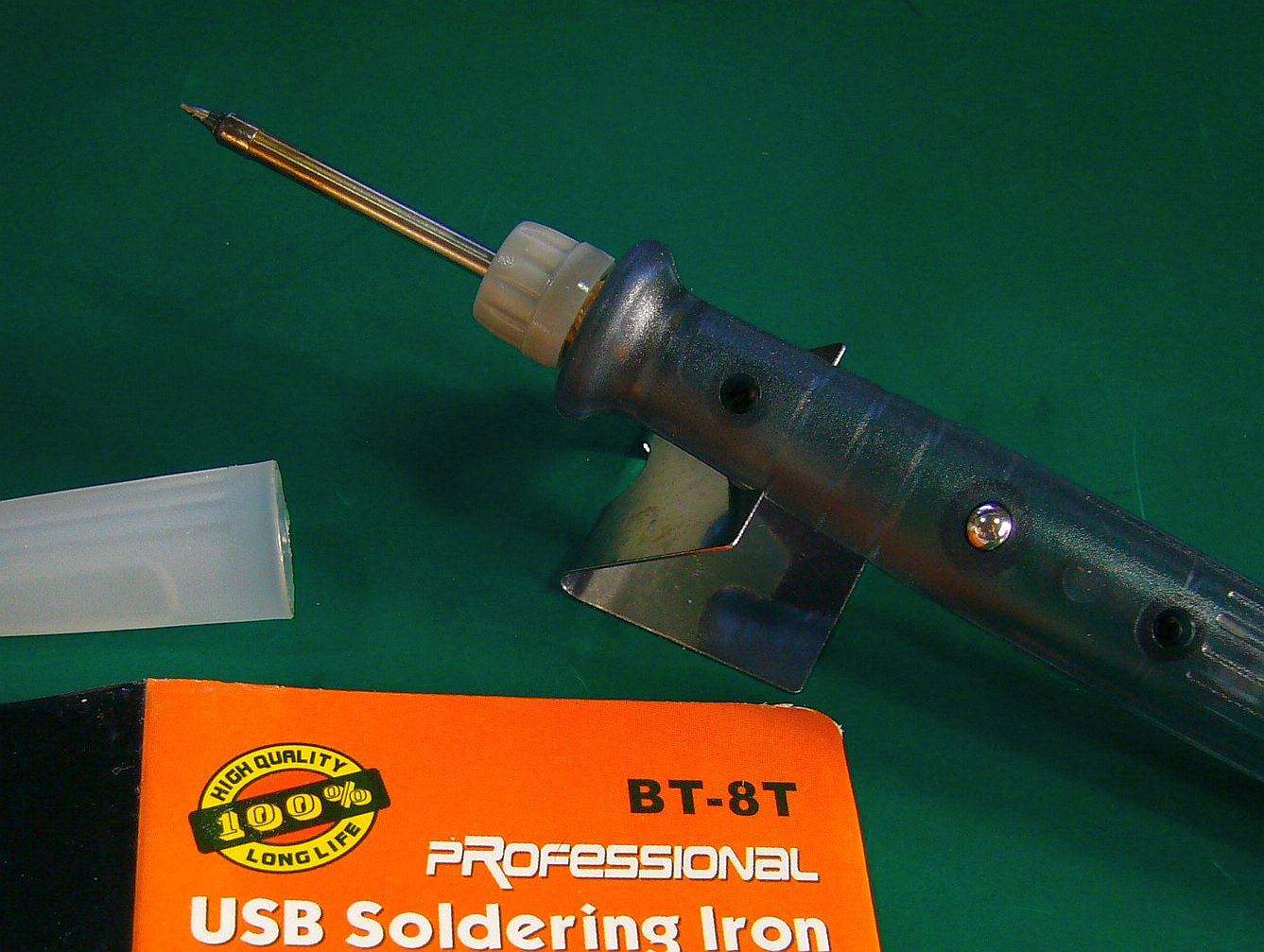
偶々、この「超小型半田鏝:BT-8T」を見掛けたので、買ってみた。(図1 $6.45送料込み、発注/PayPal支払い後、約20日で着荷)
(私が、超小型と呼んだのは、これ以上に小さいと、実用性は無いと思ったからだが、もしかしたら、あるかな?)
電源は、"USB 5V"で、消費パワーはmax8Wだそうな。「ACアダプタ」は、2A以上のものが必要らしい。
試しに、"5V, 0.5A"のアダプタでやってみたら、熱くはなるが、やはり、"パンチ不足"のようだ。
それで、これには、(手持ちの)"5V, 3A"の「ACアダプタ」を使うことにした。
"鏝先温度"は、「小プッシュ・ボタン」で3段階切替可能で、"ボタンの長押し"で、電源のON/OFFになる方式だが、これは、切り替え易くて、グッド!
最高温度は、多分、400℃以上になっているのではないかと思うが、正確さは不明。
「FLIR ONE」+「iPhone 5S」で見ると、高温度部は黒くなってしまっている。(図2[クリック])
通常の使用では、(最低温度の)緑色(LED点灯状態)で置いておき、半田付けを実行する際に(最高温度の)赤色(LE点灯状態)にするのが良さそうだ。
私の場合、中間の温度(青紫色?)は、まだ使っていないが、必要度は不明。

+++ 良い点・悪い点 +++
鏝先が細いので、"ピン・ポイント"で半田付けが出来るのは、素晴らしい!
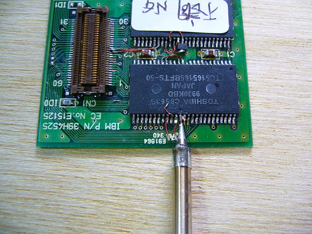
反面、スポット状に半田が早く融けても、その周りまで融かすには、時間が掛かる。(図3)
まぁ、これは"仕方がないこと"で、後は"習熟"の問題かもしれない。
加えて、"仕方がないこと"の他一つに、「電源コード」の"太さ"がある。
鏝本体が小さくて軽い為に、そのまま置いておくと、「電源コード」に引きずられて、机上から落ちてしまうことが多い。
これの対策には、"固定出来る置台"や"柔らかな電源コード"を、用意するのが良いのかもしれない。
百均グッズの「巻き取り式コード」を試してみた。(図4[クリック])
長期間の使用感ではないが、これでも使用可能な感じだ。
(付属ケーブルは約1mだが、この巻き取り式は約75㎝で、少し短い感じはある。通常の60W半田鏝のコードは、約130cmで、"短さ"などは感じないが、"太さ"は感じる。z(^^;)
尚、(壊したくないので、)ノートPCの「USBポート」では試していない。
が、過負荷になるので、多分、「USBポート」は壊れるだろうな。
...暫く、これで、熱容量の大きい基板への半田付けで悪戦苦闘した挙句、通常使っている大きい60Wの半田鏝に替えたら、途端に、瞬く間に処理が終わったので、ほっとした。
細かい作業は、し難いものの、やはり、パワーの大きな半田鏝の方が、適用範囲が広いから、具合が良い!
この超小型は、使い方が限られそう。
Ultra-small soldering iron Buy [2021/04/29]
![Fig.1 : Ultra-small soldering iron BT-8 I bought this time [click]→Fig.2 : The tip temperature is 400℃ or more ?](fig/msl0429a.jpg)
+++ For surface mounting ? +++
The previously bought " Small soldering iron: BP650MP " is quite convenient for minor "soldering corrections" etc. So I was also interested in other smaller versions.
I happened to see this "ultra-small soldering iron : BT-8T ", so I bought it. ( Fig.1 $ 6.45 Includes shipping, arrives in about 20 days after ordering/temporary payment)
(I called it ultra-compact because I thought it wouldn't be practical if it was smaller than this, but maybe there is one ?)
The power supply is "USB 5V" and the power consumption is max 8W. It seems that the "AC adapter" needs to be 2A or more.
I tried it with a "5V, 0.5A" adapter and it got hot, but it still seems to be "insufficient punch".
So I decided to use the (on hand) "5V, 3A : AC adapter" for this.
The "tip temperature" can be switched in 3 steps with the "small push button", and the power can be turned on/off by pressing and holding the button with few seconds, but this is easy to switch and good !
I think the maximum temperature is probably above 400°C, but the accuracy is unknown.
Looking at " FLIR ONE " + " iPhone 5S ", the high temperature part has turned black. (Fig.2 [click] )
In normal use, it seems better to leave it in green (LED lit state) (at the lowest temperature) and red (LED lit state) (highest temperature) when performing soldering.
In my case, I haven't used the intermediate temperature (blue-purple?) Yet, but I don't know the necessity.
![Fig.3 : One leg pin is OK! But [click]→Fig.4 : Easy to replace the tip](fig/msl0429c.jpg)
+++ Good points/bad points +++
Since the tip of the iron is thin, it is wonderful to be able to solder with "pin points" !
On the other hand, even if the solder melts quickly in a spot shape, it takes time to melt around it. ( Fig.3 )
Well, this is "unavoidable", and the rest may be a matter of "proficiency".
In addition, there is the "thickness" of the "power cord" in addition to the "unavoidable thing".
Because the main body of the iron is small and light, if it is left as it is, it will often be dragged by the "power cord" and fall off the desk.
As a countermeasure for this, it may be better to prepare a "fixable stand" or a "soft power cord".
I tried the "roll-up cord" of 100-yen goods. ( Fig.4 [click] )
It doesn't feel like it's been used for a long time, but it still feels like it can be used.
(The attached cable is about 1 m, but this rewind type is about 75 cm, and it feels a little short. The cord of a normal 60 W soldering iron is about 130 cm, and I do not feel "shortness", but "thickness" "I feel. z(^^;)
I haven't tried it on the "USB port" of my laptop PC (because I don't want to break it). If I'll use, it will become overloaded and probably break.
... For a while, I struggled with soldering to a board with a large heat capacity, and after that I replaced it with the large 60W soldering iron that I usually use, I was relieved that the processing was completed in short time.
Although it is difficult to do detailed work, the soldering iron with high power has a wider range of application, so it is in good condition!
This ultra-compact seems to be limited in usage.
液晶入替3種 楽悩 [to English Note] [2021/04/06]
![図1:STN-LCD画面不良のNo.13:杉 [クリック]→図2:画面表示のみが不良](fig/msl0406a.jpg)
+++ 「No.13:杉」の改装 +++
手持ちの「PC110」群の動作状況をチェックしていて、「No.13:杉」(T.Sさんからの頂き物)の表示が、悪い状態のままであるのが気になった。(図1)
いや、これはわざと、"正規の劣化見本品"として保存しておくつもりだったのだけれど。
だが、"動作良好"の状況からは、このまま温存しておくのでは、何だか勿体無い。(図2[クリック])
それに、動作チェックの際には、常に、「外部ディスプレイ」の支援が必要なのに、「外部ディスプレイ」への切り替えが、何故か、スムーズではない。
闇雲にキーを押していたら、勝手に"テスト・モード"に入っていて、時間を置いてピッピピッピと鳴いていたりする。
だが、その状況は見えないままだ。
やはり、表示部(液晶)を入れ替えた方が良いだろうという気持ちに傾いている。
![図3:3種の置き換え画面案 [クリック]→図4:FSTN-LCD案もあり得る、が](fig/msl0406c.jpg)
+++ FSTN-LCDも悪くは無いが +++
これまで、劣化した「液晶モジュール」を、入れ換える試みをして来たが、未だこれがベストだという形が得られていない。
いずれも一長一短ある。(図3)
「5型WVGA-TFT-LCD」(左側)は、明るくて、画像は鮮明だ。
前枠(ベゼル)の加工が不要で、付け加えるのは「中継基板」と「プログラムct65535e、ct65535w」だけだ。
だが、画面が少し小さくなるので、前面の"見栄え"はあまり良くない。
「FSTN-LCD」(中央)は、(下準備として)液晶両面の劣化膜の剥離作業が必要だが、下手をするとモジュールを壊す危険性が高い。
「制御基板」が不良化している場合、修理が難しいか、時には再生不能だが、事前の見極めは、難しい。
更に、輝度アップの為に、適当な「レンズ・シート」の用意や、「LEDバックライト」への改善も必要だ。
だが、「中継基板」は不要で、前の窓枠は、元のままで良いので、"見栄え"も悪くない。(図4[クリック])
出来れば、これにしたいが、今は加工作業面で、あまり自信が無い。
「6型WVGA-TFT-LCD」(右側)は、画面は明るくて鮮明だし、文字なども少し大きくて見易いので、私にはこれが一番良さそうに見える。
だが、「中継基板」は必要だし、前枠の加工が必要で、プログラムによる"画面の右寄せ"処置に、未だ課題が残っている。
尚、これ以外に、「VGA-TFT-LCD」も検討していたが、「中継基板」の設計が難しいし、横幅が元の前枠よりもかなり狭いので、"見栄え"は良くない。
新たにベゼルを作る案も持っていたが、「IBMロゴ」を、無断で印刷したり、シールを貼り付けるのも、気が引けるし、正式に許可を受けるのも、煩わしい。
まぁ、こういったことを、あれこれ楽しく悩んでいるのが、当苑の現状だ。
3 types of LCD replacement, worry with fun [2021/04/07]
![Fig.1 : STN-LCD screen defect No.13: Sugi [click]→Fig.2 : Only screen display is defective](fig/msl0406a.jpg)
+++ "No.13:Sugi/Cedar" refurbishment +++
I'm checking the operating status of my " PC110 " group, and "No.13:Sugi/Cedar" (I was worried that the display of Mr." T.S 's gift) was still in a bad state. (Fig.1)
No, I intended to keep this as a "genuine deterioration sample".
However, from the situation of "good operation", it is a waste to keep it as it is. (Fig.2 [click])
Besides, when checking the operation, the support of the "external display" is always required, but the switching to the "external display" is not smooth for some reason.
If I was pressing a key in the dark clouds, I would be in "test mode" without permission, and after a while, it would beep.
However, the situation remains invisible.
After all, I am inclined to feel that it would be better to replace the display unit (liquid crystal).
![Fig.3 : Three types of replacement screen proposals [click]→Fig.4 : FSTN-LCD proposals are possible, but](fig/msl0406c.jpg)
+++ FSTN-LCD is not so bad, but +++
So far, I have tried to replace the deteriorated "liquid crystal module", but I have not yet obtained the best form.
Both have advantages and disadvantages. (Fig.3)
The " 5-inch WVGA-TFT-LCD " (on the left) is bright and the image is clear.
There is no need to process the front frame (bezel), and only " relay board " and "program ct65535e, ct65535w " are added.
However, the screen is a little smaller, so the "look" on the front is not so good.
" FSTN-LCD " (center) requires peeling work of the deteriorated film on both sides of the liquid crystal (as a preliminary preparation), and there is a high risk of damaging the module if it is not done well.
If the "control board" is defective, it is difficult to repair or sometimes it is not reproducible, but it is difficult to determine in advance.
Furthermore, in order to increase the brightness, it is necessary to prepare an appropriate "lens sheet" and improve with the "LED backlight".
However, the " relay board " is unnecessary, and the front frame can be left as it is, so the "look" is not bad. (Fig.4 [click])
I'd like to do this if possible, but I'm not very confident about the processing and/or repair work right now.
The " 6-inch WVGA-TFT-LCD " (on the right) has a bright and clear screen, and the characters are a little biggger and easy to see, so this seems to be the best for me.
However, " Relay board " is required, and the front frame needs to be processed. Programmatic "right-aligned screen" treatment. There are still issues.
In addition to those, I was also considering " VGA-TFT-LCD ", but it was difficult to design the " relay board " and the width was the original window frame. It's much narrower than, so it doesn't look good.
I had a plan to make a new bezel initially, but I'm hold yet.
Because, to print of or to put label of the " IBM logo" personally without any permission are hesitated, but also getting officially permission might be a hassle.
Well, my current situation is that I'm having a lot of fun worrying about these things.