[2005.05.05]
内蔵メモリを8MB化しました ↓↓↓[English Note]↓↓↓
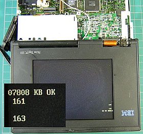
久々の大手術に挑戦しました。それと云うのも、「一言板」での−へろへろさんのお話−「小細工無しで32MBが立ち上がるらしい」に興味があったからです。(補助回路無し?補助ソフト不要?)
それには、内部メモリの8MB化が必須のようなので、どうしても本体を弄らねばなりません。以前は、本体内部を触る事は極力避けて来ましたが、最近では腕が落ちる一方?のようなので、出来る内に思い切ってやってみる事にしました。
今回で3度目の内部メモリ8MB化は・・・無事(/有事?)成功!これで2勝1敗となりました。
拡張メモリとの組み合せをちょこっと調べてみましたが、本格的な32MB化の作業は次に残して、取り敢えずここ迄で祝杯です。v(^-^)
−−−−−−−−−−−−−−−−−−−−−−−−−
+++ 処置あれこれ +++
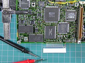
先ず主基板を取り出した上で、4MBメモリの上に同種の16160(実は、18160でした!)を(向きを間違えないように、積載。
チップ半田付けの際に小液晶(液晶インジケータ・パネル)が邪魔なので、そっと手前に曲げて、作業がやり易いようにしました。
まぁ、半田付けそのものはそれ程難しくはありませんが、問題は必ず発生する(?)小ミスです。今回もやはり、2件ばかりありました。
一旦仮組みして、動作を見た結果、
1.8MBにならない(4MBのまま)
2.主画面に表示が出ない(小液晶には、ACや電池マークは出る)
となって、どちらもよくよく調べたら、足ピンの半田付け不良が原因。
1.は、付いたようで付いていなかったピンが1本残。2.は、下側奥でピン間ショート。
半田付け状態の確認は、かなり丁寧にやったつもりだったのですが、結果的には不充分だった事が露見しました。(x_x;?
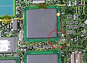
配線箇所などは、ぽんたさん処(Flat Out!)の「うるとらまんPC 」や、書かれた記事(「トランジスタ技術2002年7月号 P284〜」)などが大変参考になります。
配線には、0.25mmΦのポリウレタン線を使いました。途中のキンクや皮膜剥がれの心配もありますが、丁寧に扱えば大丈夫。それに、何と云っても端子への半田付けが、多芯のビニール線などよりずっと楽です。(左/上の写真<クリック>で、その様子)
後、面倒だったのは、ナイフで表面を削ってコントローラの(左写真では、右下から5番目)端子を露出させる事。これには結構根気が必要でした。
その端子位置は、端から5番目。端子の勘定で迷ったら、ランド/ピンの5番目で!
+++ 失策と対策 +++
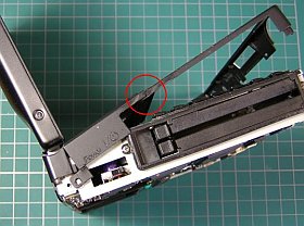
今回、キーボード枠の取外し途中で、以前接着した箇所をまた折ってしまいました。(どうも、当苑のプラスチック部の接着は長持ちしたためしがありません。特に強度が必要な箇所ではダメですねぇ。
ま、後で組み上げたら、この箇所は両側から押されるので、きちんと合わさっています。目障りですが実害は無いので我慢しましょう)
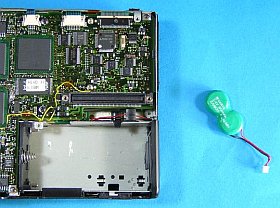
今回中を開けたついでに、この際ですから、液漏れが怖いひょうたん電池を取り除く事にしました。
まだ、電池の外見は奇麗なので少し勿体無い気もするのですが、筐体側を改造・開口してあるので、どうしても必要なら再取付けは出来るでしょう。
| 容量(内蔵+拡張) | 拡張板 | Bk0 | Bk1 | Bk2 | Bk3 | 全量 |
|---|
| 8MB+0MB | 無し | B | 3 | 0 | 0 | 8MB |
| 8MB+4MB | 標準型 | B | 3 | B | 0 | 12MB |
| 8MB+8MB | 亀々型 | B | 3 | B | B | 16MB |
| 8MB+16MB | 市販橙 | B | 3 | C | C | 24MB |
| 8MB+16MB | 市販黒 | B | 3 | C | C | 24MB |
| 8MB+16MB | 自家製1 | B | 0 | D | 0 | 20MB |
| 8MB+16MB | 自家製2 | B | 0 | 5 | 0 | 20MB |
| 8MB+8MB | 自家製3 | B | 3 | C | 0 | 16MB |
|---|
+++ 拡張メモリとの組み合せ +++
バンク0とバンク1がそれぞれ4MBで埋まったので、拡張メモリと組み合せた場合のメモリ・レジスタの内容やメモリ全量を、自作の補助ソフトover16sで見てみました。
市販品(橙色、黒色)の拡張16MB(8ビット幅FPチップ8個搭載品)だと全量は24MBになるのに、自家製の拡張16MB(65165)や32MB/2(13165)だと、全量が20MBになります。その場合バンク1(Bk1)のメモリ量はゼロになっています。(はて?)
ここで気が付いたのですが、もしかしたらBIOSがバンク1の4MBを認識する前にバンク2の16MBを認識してしまうと、バンク1の内容は無視するのでしょうか?
それなら、兎に角8MBの拡張メモリを用意して調べてみたいですね。
・・・ と云う事で、急遽16MB板(65165相当チップ搭載)を改造(A11への配線を切り離)した8MB自家製3でやってみました。これだと、ちゃんとバンク1も活きていてメモリ全量も16MBなっています。
次の計画?
次のステップは、拡張メモリ板上に(手持ち最後の)65160チップを4個載せて、8MB+16MB構成にしたものを作ろうと思っています。
これで直行32MBが出来れば面白いのですが。でも、32MBフルだと256色が出せないだろうと思うので、全量で28MBに出来ないかも考えてみたいですね。(無理かな?)
(まぁ、後は「進めぇ〜!.....ひょうたん島〜♪」です)
Built-in memory has been increased to 8MB

I tried major surgery for the first time in a while.
I took on the challenge of major surgery after a long time. That's because I was interested in the story Mr.HeroHero on the "One Line Board" - "It seems that 32MB can be started without any tricks." (No auxiliary circuit? No auxiliary software?)
To do that, it seems that the internal memory needs to be increased to 8MB, so I have to tinker with the main unit. In the past, I avoided touching the inside of the main unit as much as possible, but recently it seems that my skills are getting worse? So I decided to take the plunge and do it while I can.
This was my third attempt to increase the internal memory to 8MB... and it was a success (or was it an emergency?)! That makes it 2 wins and 1 loss.
I did a little research on the combination with the expansion memory, but I'll leave the actual work of increasing it to 32MB for next time, so for now, I'll celebrate myself. v(^-^;
−−−−−−−−−−−−−−−−−−−−−−−−−−
![Check the Tortoise Wiring carefully [click] to see the Tortoise from a diagonal side view](fig/inmm8m2.jpg)
++++ Various Solutions ++++
First, I removed the main board, then placed the same type of 16160 (actually, it was a 18160!) on top of the 4MB memory (taking care not to get it facing the wrong way).
When soldering the chips, the small LCD (LCD indicator panel) gets in the way, so I gently bent it forward to make it easier to work on.
Well, the soldering itself isn't that difficult, but it's the small mistakes that always cause problems (?). Now There were two problems this time.
After assembling it temporarily and checking the operation,
1.It did not reach 8MB (remained at 4MB)
2.The main screen did not display (AC and battery marks appeared on the small LCD screen)
After examining both of them carefully, it was found that the cause was poor soldering of the pins.
About 1. There was one pin left that looked like it was attached but was not.
About 2. There was a short between the pins at the bottom back.
I thought I had checked the soldering condition very carefully, but it turned out that it was not sufficient. (x_x;?

For wiring locations, etc., please see Ponta-san's Place (Flat Out! )'s "Ultraman PC" and written articles ("Transistor Technology July 2002 issue, p. 284~") are very helpful.
I used 0.25mm diameter polyurethane wire for the wiring. There is a concern that it may kink or peel off, but if you handle it carefully, it's fine. And, most importantly, it is much easier to solder to the terminals than multi-core vinyl wire. (Click the photo on the left to see how it looks)
Then, the most troublesome thing was scraping the surface with a knife to expose the terminal of the controller (the fifth one from the bottom right in the photo on the left). This required quite a bit of patience.
The terminal is the fifth one from the end. If you are unsure about the terminal count, use the 5th land/pin!

++++ Mistakes and countermeasures++++
This time, while I was removing the keyboard frame, I broke the part that I had previously glued. (I've never seen the adhesive on the plastic parts of our garden last long. Especially not in places that need strength.
Well, when I put it together later, this part will be pressed from both sides, so it will fit together properly. It's an eyesore, but it doesn't do any real harm, so I'll just have to put up with it.)

While I was opening it up this time, I decided to remove the gourd battery, which I was worried would leak.
The battery still looks nice, so it's a bit of a waste, but since I modified and opened the case, I'm sure I can reinstall it if I need to.
| Capacity (built-in + expansion) | Expansion board | Bk0 | Bk1 | Bk2 | Bk3 | Total |
|---|
| 8MB+0MB | none | B | 3 | 0 | 0 | 8MB |
| 8MB+4MB | standard | B | 3 | B | 0 | 12MB |
| 8MB+8MB | turtle type | B | 3 | B | B | 16MB |
| 8MB+16MB | CommercialOrange | B | 3 | C | C | 24MB |
| 8MB+16MB | Commercial black | B | 3 | C | C | 24MB |
| 8MB+16MB | Homemade 1 | B | 0 | D | 0 | 20MB |
| 8MB+16MB | Homemade 2 | B | 0 | 5 | 0 | 20MB |
| 8MB+8MB | Homemade 3 | B | 3 | C | 0 | 16MB |
|---|
++++ Combination with extended memory++++
Since Bank 0 and Bank 1 were filled with 4MB each, I used my own auxiliary software over16s to check the memory register contents and total memory when combined with extended memory.
The total amount is 24MB with the commercially available (orange and black) extended 16MB (with eight 8-bit FP chips), but the total amount is 20MB with the homemade extended 16MB (65165) and 32MB/2 (13165). In that case, the memory capacity of bank 1 (Bk1) is zero. (Huh?)
At this point, I realized that if the BIOS recognizes the 16MB of bank 2 before recognizing the 4MB of bank 1, perhaps the contents of bank 1 will be ignored?
If that's the case, I'd like to try preparing 8MB of expansion memory.
...So I quickly modified a 16MB board (equipped with a 65165 equivalent chip) (disconnected the wiring to A11) and tried it with an 8MB homemade3. With this, bank 1 is still active and the total memory capacity is 16MB.
Next Plan?
The next step is to put four 65160 chips (the last ones I have) on the expansion memory board, and make an 8MB+16MB configuration.
It would be interesting if I could get 32MB directly with this. However, I don't think I could get 256 colors with the full 32MB, so I'd like to see if I can make it 28MB in total. (Is that possible?)
(Anyway, the rest is "Go ahead !")


![Check the Tortoise Wiring carefully [click] to see the Tortoise from a diagonal side view](fig/inmm8m2.jpg)


