[2003/06/23]
32MB拡張メモリ最終版のまとめ

先回の試み以後ひょんな事から、初期16MB、レジスタ書直しで28MBまで使用できる回路が実現できました。英語版の方では、既に記事にしてありますが、改めて、(備忘のためにも)ここでまとめておきます。
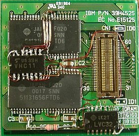
製作手法は、PC110用4MB拡張メモリ板上のメモリ・チップを取り外して、その替わりに128MbitsのDRAMチップを載せて、32MB拡張メモリにします。
この128MbitsDRAMは、ノート用128MBメモリ・モジュール(EDOタイプ)などに搭載されているチップ(51131656)を、高温ブロアで取り外して用いました。
-----------------------------
Last attempt Since then, by some chance, I have been able to create a circuit that can use up to 16MB initially and up to 28MB by rewriting the registers. English version has already written an article about it, but I'll summarize it here again (as a reminder).
The manufacturing method is to remove the memory chip on the 4MB expansion memory board for PC110, and replace it with a 128Mbits DRAM chip, making it 32MB expansion memory.
This 128Mbits DRAM is a chip (51131656 installed in 128MB memory module for notebook (EDO type) ) was removed using a high-temperature blower.
−−−−−−−−−−−−−−−−−−−−−−−−−
回路構成 Circuit

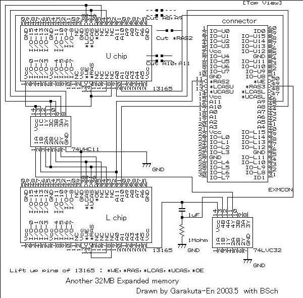
4MB拡張メモリ板では、バンク2用とバンク3用の2つのバンク選択用信号(*RAS2,*RAS3)が使用可能なのですが、128MbitsDRAMには、それらをそのまま接続できる端子がありません。でも、*RAS2信号をA11として使えば、16MB上下(/左右?)ブロックを切り替えられる事が分かりました。(HeroHeroさんによると、*RAS3を使う方法もあるそうです)
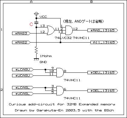
他方、チップ側の*RAS入力には、ANDゲート経由で*RAS2と*RAS3信号の両方を与えています。
現状では、128MbitsDRAMとして(FPタイプがあればベストなのですが)EDOタイプしか入手できないので、これをFPモドキにする事と、それによって起こる弊害を回避するために、ANDゲートによる補助回路を入れています。
一番重要なのは、初期立ち上がり時に、拡張メモリ量が20MB超だとBIOSが正常に立ち上がらない事です。
-----------------------------
On the 4MB expansion memory board, two bank selection signals (*RAS2, *RAS3) for bank 2 and bank 3 can be used, but 128Mbits DRAM does not have a terminal that can directly connect them.
However, I found out that if I use *RAS2 signal as A11, I can switch between 16MB upper and lower (/left and right?) blocks. (According to HeroHero, there is also a method using *RAS3 Apparently there is)
On the other hand, both *RAS2 and *RAS3 signals are applied to the *RAS input on the chip side via an AND gate.
Currently, only the EDO type is available as 128Mbits DRAM (it would be best if there was an FP type), so I would like to make this FP like and thereby In order to avoid adverse effects, we have included an auxiliary circuit using an AND gate.
The most important thing is that the BIOS will not start properly if the amount of expanded memory exceeds 20MB during initial startup.

だから、立ち上がり初期には半分の16MBだけで動作させ、立ち上がった時点で"レジスタ書換えプログラム"でメモリ制御レジスタを書直して、残りを有効にします。そのために、初期遅延用のC・R(容量と抵抗)と封鎖用のORゲート回路を使用しています。
レジスタ書直し後、一旦プログラムでソフト・リセットを掛けて、書換えたレジスタの値をシステムに認識させます。
(が、この再認識過程の詳細については、残念ながら殆ど知りません)
-----------------------------
Therefore, at the beginning of startup, it operates with only half of 16MB, and once it starts up, it rewrites the memory control register with a "register rewrite program" to enable the rest. For this purpose, we use C・R (capacitance and resistance) for initial delay and OR gate circuit for blockade.
After rewriting the register, apply a soft reset using the program to make the system recognize the rewritten register value.
(However, unfortunately, I don't know much about the details of this re-recognition process.)
部品や配線 Parts and wiring

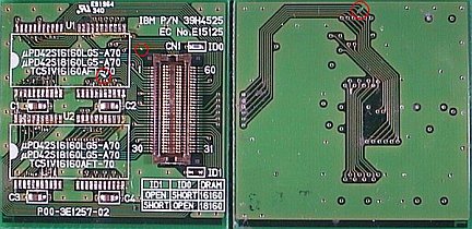
実際の製作では、128Mbitsチップ搭載や回路配線に先立って、3個所5線のパターン・カットを済ませておく必要があります。(左上図の左、および右写真参照)
ANDゲートは、74HC08,74HC11など低速タイプを使っていますが、これは薄型なのでこれらを選んだまでで、本当はORゲートに使った74VHC32や74LVC32などと同様の高速タイプが望ましいと思います。
C,Rは、初期遅延用のCは0.3〜3μFの範囲、Rは1〜3MΩの範囲で、C・R積が0.3〜3秒位の範囲なら良いようです。
配線には、0.2mmφのポリウレタン(?多分)単線を用い、皮膜は融けた状態の半田に突っ込んで焼いて剥がします。それで、同時に表面に半田皮膜ができるので、それを利用して半田付けを行いました。(尚、配線は0.3mmφだと、少し硬すぎ)
-----------------------------
In actual production, it is necessary to complete the pattern cutting of 5 wires in 3 locations before mounting the 128Mbits chip and wiring the circuit. (See the left and right photos in the upper left picture)
I use low-speed types of AND gates such as 74HC08 and 74HC11, but I chose these because they are thin, and I actually use them for OR gates. I think a high-speed type like 74VHC32 or 74LVC32 is desirable.
As for C and R, C for initial delay is in the range of 0.3 to 3μF, R is in the range of 1 to 3MΩ, and it seems to be good if the C・R product is in the range of about 0.3 to 3 seconds.
For the wiring, use a 0.2mmφ polyurethane (maybe) single wire, and peel it off by sticking it into the melted solder and baking it. At the same time, a solder film was formed on the surface, so I used that to solder. (In addition, the wiring is a little too hard if it is 0.3mmφ)
レジスタ書換えプログラム Register rewrite program
これは、アセンブラで組んだ小さな自家製プログラムです。
機能として、メモリ・レジスタ内容の表示、バンク毎の書換えがあります。
ただ、ここに示した32MB拡張メモリでは、第3バンク(最後尾)だけしか書換えられません。他のバンクを書換えると、大抵、PC110が暴走します。
このプログラムは、レジスタを書換えた後、一度ソフト・リセットします(FFFF0000hへジャンプ)。その後、レジスタ内容が指定通りに書換わっていれば、そのまま通過させて通常のOS動作に戻します。
これは、手動ででも起動できますが、autoexec.batに入れて、操作を自動化する事もできます。
書式: over16s [///c] (over16sの置き場所は、こちら)
over16s ・・・ オプション無しの場合、レジスタ内容の表示 例:下表
over16s ///c ・・・ 第3バンクのメモリ値指定 例:c=8MB (トータルで28MB)
ここで、dは16MB、 cは8MB、bは4MBを表わす
(d,c,bの代わりに5,4,3を用いてもよい)
-----------------------------
This is a small homemade program written iwith assembler.
Functions include displaying memory register contents and rewriting each bank.
However, with the 32MB expanded memory shown here, only the 3rd bank (last) can be rewritten. If it rewrite other banks, PC110 will usually go out of control.
After rewriting the register, this program performs a soft reset (jump to FFFF0000h).
After that, if the register contents have been rewritten as specified, the program will pass through and return to normal OS operation.
It can be started manually, but it can also be placed in autoexec.bat to automate operations.
Format: over16s [///c] /src/verinf.html">here)
over16s Display register contents Example: Table below
over16s ///c ・・・ Specification of memory value for the 3rd bank Example: c=8MB (28MB in total)
Here, d stands for 16MB, c stands for 8MB, and b stands for 4MB
(5,4,d,c,b >3 may also be used)
後処理 after treatings
配線は、かなり細いので、誤って引っ掛かけたりすると切れる恐れがあります。そこで、DIY店などで入手が容易な(速乾性)液状ニスを、細筆で塗って配線群を固定しました。(本当は、高周波ニスなどの方がいいのですが...)
偶々一度、垂らしたニスの量が多すぎたため、コネクタのピンの間から接触部まで這い上がって、ピン表面に薄い絶縁膜ができたようで、マウスが動かなくなるなどの異常動作が発生しました。
しかし、何度か抜き差しを繰り返していると直っていましたので、それほど心配する事でもなかったようです。
-----------------------------
The wires are quite thin, so there is a risk of them breaking when I accidentally snag them. Therefore, I used a quick-drying liquid varnish, which is easily available at DIY stores, to be applied with a fine brush to secure the wiring group. (Actually, High-frequency varnish would be better, but...)
By chance, I dropped too much varnish, and it crawled up between the pins of the connector to the contact area, forming a thin insulating film on the surface of the pins, causing abnormal behavior such as the mouse not working.
However, it was fixed after I re-inserted and unplugged it several times, so it didn't seem to be much of a concerThe wires are quite thin, so there is a risk of them breaking with snagging. Therefore, I used a quick-drying liquid varnish, which is easily available at DIY stores, to be applied with a fine brush to secure the wiring group. (Actually, High-frequency varnish would be better.)
By chance, I dropped too much varnish, and it crawled up between the pins of the connector to the contact area, forming a thin insulating film on the surface of the pins, causing abnormal behavior such as the mouse not working.
However, it was fixed after I re-inserted and unplugged it several times, so it didn't seem to be much of a concern.


