�Ƃ茾�W�@�ߘa��N�㌎��
�g�僋�[�y�@���� �@[English Note]�@�@[2020/09/15]

�{�{�{�@�ǂ����[�y���~�������@�{�{�{
����A���E���{���ŁA�ʔ������ȃ��[�y�����t�����̂Ŕ����Ă݂��B�i���U�P�O�ō��݁j
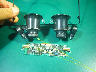
�������A"�����̋����^�œ_����"���A��cm�قǂ������Ȃ��B�i�}�P�j
����ł́A���ׂ̍�����Ɨp�ɂ͎g���Ȃ��ł͂Ȃ����I
���������A�́A���v���̂������A����Ȋዾ���|���āu���v�v�̏C�������Ă����̂��v���o�����B
���̎����A���v���ዾ�̋߂��܂Ŏ����ė��Ĕ`���Ă������A��������͂肻�����������I
���́A0.5mm�s�b�`�́u�R�l�N�^�v��0.2mm�́u�����v�Ȃǂ��������Ƃ���ƁA�{���̍������[�y���~�����Ȃ�B
����ŁA�F�X�g�������Ă���̂����A��������{�����������̂́A���c�t���̍ۂɁA���c�W�����錄�Ԃ�����Ȃ��č���̂��B�i�}�Q�m�N���b�N�n�j
����ɁA���肪�g���Ȃ��̂��ق��̂ŁA���̎��ɂ́u�w�b�h�E���[�y�v���g�����A�����"�{��"��"����"�Ƃ̌��ˍ����ɂȂ�B
�����ŁA�悭�v���̂́A"�]�����^�w�b�h�E���[�y"���Ė������̂��H�ƁB
�y���āA���삪�������������āA�{����5�{����15�{�A�o����ΉςŁA"���[�y"��"�Ώە�"�Ƃ̋�����10cm�ȏ�ŁA����Ɉ����Ȃ��̂��~�����I
�D�D�D�ł��A����ȍ�Ƃ��D��ł���悤�Ȑl�́A���������Ȃ�����A���i�ɂ́A������낤�ȁB
�����ō���Ȃ�A����Ă݂������A�܂��������ȁB
Expanded loupe buying [2020/09/15]

+++ I want a good magnifying glass, but +++
The other day, I found a magnifying glass that looks interesting in Nipponbashi, Osaka, so I bought it. (\ 610 including tax)
However, the "clear vision distance/focal length" can only be obtained by a few centimeters. (Fig_1)
Isn't this usable for my detailed work !
By the way, I remembered that a long time ago, an uncle of a watchmaker wore such glasses and repaired a "watch".
At that time, I brought my watch close to my glasses and looked into it, but was that so ?
In fact, when trying to handle 0.5mm pitch "connectors" and 0.2mm "copper wires", you want a magnifying glass with high magnification.
That's why I use them in various ways, but the ones with high magnification are in trouble because there is not enough space for the soldering iron when soldering. (Fig_2 [click])
Besides, I'm afraid I can't use both hands, so I use a "head loupe" at that time, but this is also a trade-off between "magnification" and "gap".
So, what I often think about is the "telescope type head loupe" ?
I want something that is light, has a decent field of view, has a magnification of 5 to 15 times, is variable if possible, is gap about 10cm, and is inexpensive !
... However, there aren't many people who like that kind of work, so it would be difficult to make a product.
If I can make it myself, I would like to make it, but it is impossible.
FPC�܂�E�f���@�C�� �@[English Note]�@�@[2020/09/03]

�{�{�{�@FPC���f�������̂̓R�l�N�^�������H�@�{�{�{
���L�uPC110�v��7���@�F"�|"�́uVGA23-TFT�v���̎��݂ŁAVGA�\������肭�s���āA�uLCD�P�[�X�v��킹�����A2�̎��̂��N�����B
��́A7���@�F"�|"���̏�^�s�lj����Ă��܂������ƂƁA������́A�uVGA23-TFT�v��FPC�̈ꕔ�ɒf�����N���n�߂����Ƃ��B�i�}�P�j
�s�lj��̌��́A�ʂɏ��������A�����ł́AFPC���f�������C�������ɂ��ď����Ă����B
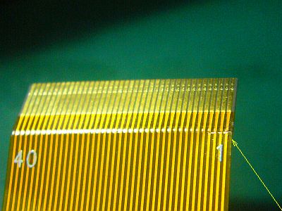
FPC�̒f���́A�����180�x�܂ŋȂ�����A�܂����̕���ȏ�Ԃɂ܂Ŗ߂������Ƃ炵���B�i�}�Q[�N���b�N]�j
FPC��180�x�Ȃ��������́A�uPC110�v��"LCD-FPC"�Ɠ����悤�Ȍ`�ɐ^�����������ƁA�y�юg�����u40�s���E�R�l�N�^�v���A"���s���^"���������Ƃ�����B
�����A"��s���^�R�l�N�^"���g���Ă���AFPC��180�x�Ȃ��Ȃ��Ă��ς͂��Ȃ̂ŁA����܂��B

�{�{�{�@0.2mm�����ł̕�C�@�{�{�{
���́A���́uVGA23-TFT���W���[���v�́A�����p�����邵���Ȃ��I�Ƃ͎v�������A�ȑO�A"0.5mm�s�b�`���Q�̐ڑ�"����K���Ă����̂ŁA�������x�͎����Ă݂悤�ƁA�C���Ɏ��g��ł݂��B
FPS�̔핢���̂ɁA�S�σO�b�Y�́u�H�|�p�J�b�^�v�̐n���A�X�ɉs�����������̂��g�����B
�o���邾�������͈͂��œ�������I�o�����A������"���c�햌"���{�����B
0.2�o���̓����́A�\�ߔ핢���ŁA����ɂ�"���c�햌"�����Ă����B
���̓������2mm�`3mm�̒����ɐ��āA����Œf������ڑ������B
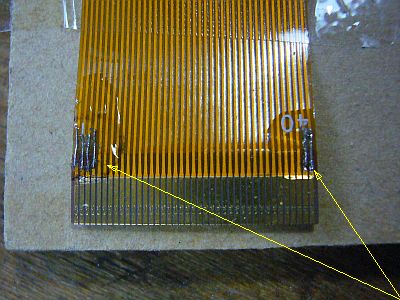
�n�߂�1�A2�{�́A�X���[�Y�ɔ��c�t���o���邪�A���̌オ����I�I�i�}�R�j
"�s���Z�b�g�̕ێ���"���A"�����̌��ߎ�"���낤�ȁB��j
�悸�A�i�s��#1,2,3,4�́j4�{������ڑ����āA���̏���u���O���d���ڒ��܁v�ŗ��߂��B
�Ƃ��낪�A���ʂ͕ρH��ʂ��t�l�������I
�s��#39,40������ƁA�������f�����Ă����̂ŁA������@�Őڑ��B
�ŏI���ʂ́A�ǍD�I�I
6���@�F"��"���g���āA�f�����o������i�}�S�m�N���b�N�n�j
�ł��A���̗l�q���ƁA���̐��Q��"�����h���Ƃ͎v���Ȃ��B��́A���ӂ��Ďg�������Ȃ����B
�������A�܂��A0.5mm�s�b�`�̐��Q�̔��c�t�����A���Ώo������̂ł��˂��B
������������AMoonlight����̌��C�����A�����Ė�����̂�������Ȃ��B�i���ӁI�j
FPC break/disconnection repair [2020/09/03]
![Fig_1 : Backlight power line was broken [click] �� Fig_2 : The cause was bending the FPS 180 degrees The purposeful](fig/msk0903a.jpg)
+++ FPC is broken due to the dirction of theconnector ? +++
Privately owned "PC110" No.7:"Bamboo" Attempted to convert to "VGA23-TFT", VGA display went well, but two accidents occurred when I covered the LCD case.
One is that No.7:"Bamboo" has failed/deteriorated, and another is One is that some of the FPCs in the "VGA23-TFT" started to break. (Fig_1)
I wrote about the case of failure separately, but here I will write about the case of repairing disconnection point of FPC.
It seems that the FPC was broken by bending it up to 180 degrees and returning it to its original flat state. (Fig_2 [click])
The cause of bending the FPC 180 degrees is that it is similar to "LCD-FPC" of "PC110", and The "40 pin connector" I used was "lower pin type".
If I was using "upper pin type connector", I wouldn't have to bend the FPC 180 degrees, so I regret it.
![Fig_3 : Connected with 0.2 mm copper wire [click] �� Fig_4 : Image display recovered on the No.6 : Pine](fig/msk0903c.jpg)
+++ Repair with 0.2mm copper wire +++
Actually, this "VGA23-TFT module" must be discarded anymore! I thought that, but I was practicing "0.5mm pitch line group connection"" before, so I'll try it again and repair it. I worked on.
To remove the FPS coating, I used a sharper sharpened blade from the "Craft Cutter" from Hyakune Collectibles.
I peeled off the longest possible area to expose the copper foil, and applied a "solder coating" there.
The 0.2 mm�� copper wire is stripped of its coating in advance and a "solder coating" is also applied to it.
The copper wire was cut into a length of about 2 mm to 3 mm, and the break was connected with it.
The first one or two can be soldered smoothly, but it is difficult after that !! (Fig_3)
"Tweezer holding power" may be the "decision factor".
First, only 4 (pins #1,2,3,4) were connected and the top was fastened with "ultraviolet curing adhesive".
However, the result is strange ? The screen was upside down !
Looking at pins #39 and 40, they were also broken, so connect using the same method.
The final result is good !!
I was able to use No.6:"Pine" to create an image �� (Fig_4 [click])
But in this situation, I don't think other lines are "intact".
After that, I have no choice but to use it carefully.
However, well, I'll be able to solder multi lines with a pitch of 0.5 mm.
Perhaps the energy of Mr.Moonlight was shared for me. (Thanks !)