独り言集 令和二年十二月版
頂き物(Walkman) 分解 [ English Note ] [2020/12/27]
 [クリック]→図2:")
先般、「Hassan」さんから頂いた物の中に、「Walkman」2台があった。
私は、"ノートPC"や"オシロスコープ"以外には、"SONY製品"を触ったことが無いという、奇癖の持ち主(?!)なのだが、今回偶々、(不動の)「Walkman」を頂いたので、"これ、幸い!"と触って、分解してみた。
実は、大柄な方(WM-2)も、一度分解してはみたが、薄型の方(WM-20)が魅力的なので、そちらの方を取り上げる。(図1)
この「WM-20」は、大変メカメカしくて/無骨そうで、今の(ツルツルの)時代には、もう流行りそうにないが、反面で、机上でのちょっとした飾り物としても、置けそうなデザインなので、私は好きだ。
動作させることは、考えていないが、一応、内部を確かめてみた。
やはり、不動の原因は、「ゴム・ベルト」の劣化だ。(図2[クリック])
しかし、それ以外にも、電気回路系の不良化があるようだが、深追いはしなかった。

+++ 分解と試験 +++
分解は、細身の「+ドライバ」だけで、用が片付くかな?と思っていたが、豈図らんや、初っ端から、「VRツマミ」を外すために、「かに目ペンチ」が必要だった。
幸い、今「百均ペンチ」が遊んでいる。これの先端を尖らせれば、代用品が出来そうだ!
さぁ、卓上グラインダの出番だ!...ガリガリガリ!で、あっという間に、出来上がり!それを使って一発で、取り外せた♪(図3)
後は、「+ドライバ」だけで、分解出来るが、実に簡単だった。
そして、再度組み立てるのも、無理なく出来た。
"精巧に、丁寧に造られているなぁ..."と感じた。
故障の原因は、やはり「ゴム・ベルト」が劣化して切れていたこともあるが、電子回路の方も、劣化しているらしい。
試験的に外部から電圧を与えて、スイッチを入れても、「モータ」が廻る気配すら無い。(図4[クリック])
これ以上の分解や再組立てに自信が無いので、それ以上の深堀りは留めた。
並行して、「ゴム・ベルト」の入手の可否を調べたら、「ヤフオク!」でも、それらしいのを見掛けた。
しかし、これ以上、食指は動かず。
全体を再組立てしたが、「TAPE」や「DOLBY NR」のスイッチなども、取り付けは難しくはなくて、実にスムーズに組み上げられた♪
こうした処が、感心した点だ。
以前から、SONY製品には、"ソニー・タイマ"という評もあるようだが、この製品は、どうだったのだろうか?
「ゴム・ベルト」などは、耐用年数の短い"消耗品"だそうだから、"無償修理期間"の設定は、きっと難しかったに違いない。
これを分解ながら、そんなことを考えていた。
Disassembly of the Walkman [2020/12/27]
Recently, among the things I received from Mr." Hassan ", there were two " Walkman ".
I have a strange my habit (?!) that I have never touched " SONY products " except "notebook PC" and "oscilloscope".
But I happened to get a (immovable) " Walkman " this time, so I pleased "This is a fortunate !", and tried disassembling it.
Actually, I tried disassembling the large one ( WM-2 ) once, but the thin one ( WM-20 ) is more attractive, so that one to take up. (Fig.1)
This " WM-20 " seems to be very mechanic/rugged, and it might not be popular anymore in now generaton.
But on the other hand, it will become a little decoration on the desk, because it is a nice design and I like it.
I'm not thinking about making it work, but for the time being, I checked the inside.
After all, the cause of immobility is the deterioration of the "rubber belt". (Fig. 2 [click])
However, other than that, there seems to be a defect in the electric circuit system, but I did not pursue it deeply.
+++ Disassembly and testing +++
Is it possible to disassemble with just a slender "+ screwdriver" ? I thought, but I needed " Crab eye pliers " to remove "VR dial" at the beginning.
Fortunately, I have a "100-yen pliers" now. when I sharpened the tip of this, I cauld make a substitute it !
Now, desktop grinder comes into play ! ... Grinding ! And it's done in no time ! I was able to twist and remove it in one shot using it ♪ (Fig.3)
After that, it can be disassembled with just "+ screwdriver", but it was really easy.
And I was able to reassemble it without difficulty.
I felt that it was exquisitely and carefully made ....
The cause of the failure was that the "rubber belt" had deteriorated and was broken, but it seems that the electronic circuit has also deteriorated.
Even if a voltage is applied from the outside on a trial basis and the switch is turned on, there is no sign that the "motor" will rotate. (Fig.4 [click])
I'm not confident in disassembling or reassembling any more, so I've stopped deep digging more over.
At the same time, when I checked the existability of "rubber belts", I found in " Yahoo Auctions !".
However, my head-stomack did not want more foods.
I reassembled the whole thing, but the switches for "TAPE" and "DOLBY NR" were not difficult to install, and they were assembled very smoothly ♪
I was impressed with this.
It seems that the SONY product has a reputation of " Sony Timer " for some time, but this product is How was it I don't ?
" Rubber belts " are said to be "consumables" with a short service life, so it must have been difficult to set the "free repair period".
I was thinking about that while disassembling this.
PC110 No.11 試す [ English Note ] [2020/12/19]

この「PC110」ジャンクは、「Hassan」さんから頂いた物の一つで、長期間放置されていたとのことだが、どのような状態になったのか、興味があった。
"外観"は、なかかな綺麗で、私の他の保有機よりも、ずっと上等だ。w(^^;(感謝!)
一応、「No.11」と番号を付した。動作が確認出来ていないので、未だ、"呼称"は付けない。
"動作状態"を見ると、電源は入り、液晶インジケータには、"IBMマークもどき"も出る。
表示部は例の"ビネガー・シンドローム"で、バックライトは点灯しているのに、表示内容は分からず。
「ポトリ」+「外部ディスプレイ」を繋いで、電源を投入すると、(F1キーを押していれば)"Easy Setup"は(必ず)起動する。
しかし、「FD(Floppy Disk)」は愚か、その他のドライブにも、全て無反応で、"I9990305エラー"になる。(図2[クリック])
極稀に、「PCカード・スロット」にセットした「HDD」上の「Win95」が起動することがあった。(図1)
しかし、その終了時に、何かの情報を書き戻す際に"誤データ"を、書き込むらしく「Win95」が壊れてしまう。
やはり、"データの読み書き"が、非常に不安定なようだ。(アナログ的不安定性、例えば"信号振幅不足"か、デジタル的不安定性例えば"ビット欠け"かは、不明)
また、通常、殆どの場合、"I9990305エラー"か、あるいは停止してカーソルだけが点滅する状態になる。(図2[クリック])
この「PCカード・スロット」からしか起動が出来ないという状況は、「No.10:"葛城"」のそれと同じだ。
でも、「No.10:"葛城"」は安定して起動するのに、こちらは、稀にしか起動しない点で、違うのだが。

+++ EASY SETUPの様子 +++
この「No.11」は、「メモリ・サイズ」表示の後、"起動ドライブ"を探すのに、随分、長い時間待ちをしているようだ。そして、"エラー"が出るまで、長く待たされる。
電源投入時に、F1キーを暫く押していると、必ず"Easy Setup"に入れるのは、良い傾向なんだが。
でも、BIOSで認識出来ている"ドライブ"は、「PCカード系」だけのようだ。(図3)
実際に、1種類ずつ、"起動ドライブ"に指定して、幾度も起動状況を試したが、いずれも起動出来なかった。
唯一、「PCカード・スロット」にセットした旧い2種のHDDで、稀に「Win95」が起動することがある。(図4[クリック])
こうした旧いHDD(Viper260、PCHDT-2GT)を使った理由は、もしかしたら、"BOOTセクタの構造"が旧くて、旧いシステムでは、読み易いかもしれないと思ったからだ。
だが、"ドライブ電流"が増えて電源部に負担を強いるから、逆に、読み難さは増えるかもしれないとも思った。
後で、「CF+PCカード・アダプタ」に替えてみたが、いずれのドライブでも、起動する頻度に、大きな差は無いように感じた。
(起動する時は起動するし、起動しない時には、"I9990305エラー"になる)

+++ 内部の様子 +++
当初、裏蓋を開けてみたが、通常旧いマシンに見られる「ひょうたん電池」の"液漏れで腐食された領域や欠落部品"が、これでは殆ど見られなかった。(図5)
それに、「ひょうたん電池」の液漏れも、(端子部を見なかったので、良くは分からないが、)左程多くは無いかもしれない。
取り敢えず、元凶に成り得る「ひょうたん電池」は、(強引に)"支え"を切り取って、取り外した。(図6[クリック])
しかし、この辺りの様子は、「No.10:"葛城"」のそれとはかなり違うので、"起動ドライブのアクセス不良"の原因は、もっと別の箇所だろうと思う。
それが、もし共通の箇所であれば、纏めて"修理"することも考えられるが、今は未だその域には達していない。
兎に角、外から出来る範囲内で、起動可能かどうかを追ってみようと思っている。
PC110 No.11 Examination [2020/12/19]
This " PC110 " junk is one of the things given by " Mr. Hassan ", and he said that this had been left for a long time (on his shelf).
So I had an curiosity for the status of this.
The " appearance " is pretty clean and much better than my other machines. w(^^; (Thanks again !)
For the time being, he numbered " No.11 ". I haven't confirmed the operation, so I haven't added a "name" yet.
When I look at " operating status ", the power is able to turn on, and the LCD indicator also shows "IBM mark-like".
The display was the "vinegar syndrome" as well known, and although the backlight was on, I didn't know what was displayed.
When I connect "Potori" + "External display" and turn on the power with pressing the " F1 key ", " Easy Setup " will (always) start .
However, "FD (Floppy Disk)" was not readable, and all other drives didn't respond, resulting in " I9990305 error ". (Fig.2 [click])
Very rarely, " Win95 " on the "HDD" set in the " PC card slot " started up. (Fig.1)
However, at the end, it seemed to write " incorrect data " when writing back some information, " Win95 ”was broken.
After all, "reading and writing data" seems to be very unstable. (It is unknown whether analog instability, for example, "insufficient signal amplitude" or digital instability, for example, "bit missing")
Also, in most cases, " I9990305 error " or stop and only the cursor blinks.
The situation that you can boot only from this "PC card slot" is that of " No.10:Katsuragi " It's the same.
However, although " No.10:Katsuragi " starts stably, this is different in that it starts only rarely.
++++ EASY SETUP ++++
This " No.11 " seems to weist for a long time to find the "boot drive" after displaying the "memory size". Then, I have to wait for a long time until " error " appears.
It's a good tendency to always enter " Easy Setup " when I hold down the F1 key for a while when powering on !
However, it seems that the only "drive" that can be recognized by the BIOS is the "PC card system". (Fig.3)
Actually, I specified each type as the "boot drive" and tried the boot status many times, but none of them could be booted.
In rare cases, " Win95 " had started up with the two types old HDDs set in the "PC card slot". (Fig.4 [click])
I imagine that the reason for using these old HDDs ( Viper260 , PCHDT-2GT ) may be that the "BOOT sector structure" is old and easy to read from the old CPU system.
However, I also thought that the difficulty of reading might increase because the "drive current" would increase and impose a burden on the power supply section.
Later, I changed to "CF + PC card adapter", but I felt that there was no big difference in the frequency of booting with any of the drives.
(When it would start, it will start, and when it does not start, it becomes " I9990305 error ")
++++ Inside view ++++
At first, I opened the rear cover, but I could hardly see the "leakage-corroded areas and missing parts" coused by the "gourd battery" that is usually found in old machines. (Fig.5)
Also, the leak of liquid of the "gourd battery" may not be as much as on the left (although I'm not sure because I didn't look at the terminals).
For the time being, the "gourd battery", which can be the cause, was (forcibly) cut off the "support" first and removed after. (Fig.6 [click])
However, the situation around here is quite different from that of " No.10:Katsuragi ", so I think the cause of "boot drive access failure" is something else.
If it is a common part, it is possible to "repair" it all together, but it has not reached that level yet.
I'll trying to find out with slowly if it can be started up within the range that can be done from the outside.
TP535E 8611 ERR 試す [ English Note ] [2020/12/17]

頂いた「TP535E」が、単なる"部品取り材"として終るか、それとも"修理可能なPC”なのかを、予備的に調べているのだが、未だ、"8611エラー"から先へ進めない状態だ。(図2[クリック])
ネットで教わった"ひょうたん電池"の端子部は、確かに、緑青が吹いていて、周りも汚れていた。
基板裏側を見ると、「DS1868(Digital Potetiometer chip)」のVcc(+5V)の"バイパス・コンデンサ"(C233)の端子付近まで、腐食。(図1)
ここは、多分、「トラック・ポイント」に関連する箇所だから、この辺りの層間配線などが腐食していると、もう救いようがないだろう。
でも、調べられるだけ調べてみよう!
兎に角、「外付けマウス」を付けて、これでカーソルを動かせないか試みた。
そのままでは動かせなかったのだが、色々試して、「DS1868」端子とその周辺のチップ部品の半田付けを追加したら、何故か、カーソルが動かせるようになった。
しかし、「トラック・ポイント」では、カーソルは動かせない!
")
実は、「DS1868」の近傍の汚れを、歯ブラシでこすり落としていたら、それまで動く気配が無かったカーソルが、「外付けマウス」で動くようになったのだ。(図3)
一応、その辺りにチップ部品群や、「DS1868」の脚ピンなどに"追加半田"をしておいたら、以後、「外付けマウス」では、安定して動作している。
他方、「トラック・ポイント」の方は、「6ピン・コネクタ」からFFCを抜いても差しても、"8611エラー"は解消せず。
因みに、"本体側端子電圧"と"トラック・ポイント側端子開放抵抗値"を調べたら、図4[クリック]のようであった。
これから判断すると、此処が"8611エラー"を引き起こしているとは思えない。
恐らく、もっと奥の方の回路だろう。
他のThinkPadのように、BIOSで「トラック・ポイント」を切り離すことが出来れば、もっと原因が掴み易いかもしれないが、「TP535E」ではここまで。
「DS1868」を交換してみる手もあるが、今回は保留だ。
TP535E 8611 ERR, Try [2020/12/17]

I'm preliminarily investigating whether the " TP535E " I received ends up as a " collection of parts " or a " repairable PC". I still can't proceed from " 8611 error ". (Fig.2 [click])
The terminal part of the "gourd battery" that I learned on the net was certainly patina, and the surroundings were also dirty.
Looking at the back side of the board, it corroded up to the vicinity of the terminal of the Vcc (+ 5V)'s "bypass capacitor" (C233) of the " DS1868 (Digital Potentiometer chip) ". (Fig.1)
This is probably a part related to the " Track Point ", so if the inter-layer wiring around here is corroded, there might be no help for it anymore.
But let's find out the fault as much as I can !
I attached an "external mouse" tried to move the cursor with it.
I couldn't move it as it was, but after trying various things and adding soldering to the " DS1868 " terminal and the chip parts around it, for some reason the cursor could be moved.
However, the cursor cannot be moved at " Track Point " !
In fact, when I scraped off the dirt near the " DS1868 " with a toothbrush, the cursor, which hadn't seemed to move until then, now moves with the "external mouse". (Fig.3)
For the time being, when I put" additional solder" on the chip parts group and on the leg pins of " DS1868 " around that area, then the " external mouse " became to operate stably.
On the other hand, " 6811 error " was not resolved even if the FFC was removed or inserted from the "6-pin connector" of the " Track Point ".
By the way, when the "main unit side terminal voltage" and the "Track Point terminal open resistance value" were examined, it was as shown in Fig.4 [click].
Judging from this, I don't think this is causing the " 8611 error ".
Probably the circuit in the back.
If I can separate the " Track Point " in the BIOS like other ThinkPad , it may be easier to grasp the cause, but that's not it for " TP535E ".
There is an idea to replace the" DS1868 ", but this time I hold out it.
頂き物(TP535E 塗装) [ English Note ] [2020/12/15]

「Hassan」さんから、"部品取り用ジャンク TP535E、PC110などは、要りませんか?"とのお申し出を頂き、どんな状態なのかと、好奇心一杯で(ダボハゼの如く)喰い付いた。
(実は、ダボハゼが、果たして、"好奇心"で餌に飛び付くのかどうかは、私は知らないが。^^;?)
いずれも、ちょっと調べた処では、電源は入るが正常動作は不可のようだ。
今回は取り敢えず、「TP535E」への対処について。
その昔、私もTP535Eジャンクは、買って、そして捨てた記録があるのだが、最近また、この辺りの機種が懐かしくなって来ている。
(先日も、「TP230Cs」などのジャンクを、再入手するつもりもないのに眺めていたりしている)
頂いた「TP535E」ジャンクは、電源は入るが、「トラック・ポインタ」が動かず、"08611エラー"で先へ進まない。(図1)
このエラーについて、「ThinkPad Club」の記事を拝見すると、今後私が調べるべき箇所が分かった。(図2[クリック])
これは、追々調べてみようと思う。
その前に、周りのベタベタ(塗装の劣化)を処置しておきたい。

"ベタベタ塗装"は、「ポータブル・ナビ機」でも、随分苦労をさせられたが、今回は、面積も広く、凸凹も多いので、かなり面倒だった。
それに、塗装層が2重になっているかどうかも分からなかったので、留め処が難しい。
今回改めて分かったのは、"エタノール/エチルアルコール"の純度が高い方が良いということ。
"コロナ騒ぎ"で、一時、安価な"消毒用エタノール"が、薬店の棚から消えてしまった。
出て来たのは、混ぜ物が多い、"消毒液(エタノール入り)"ばかり。
最近、やっと百均店にも、小瓶が見られるようになったが、これも、アルコール約60%、水40%だそうだ。
それでネバネバ面を拭おうとしたが、殆ど取れなかった。
止むを得ず、薬店で見掛けた(高価な)"消エタ"(C2H6O:76.9〜81.4vol%)を買って来た。(図4[クリック])(¥1,320税込み)
これだと、(エンボス加工の)「キッチン・タオル」に吸わせてから表面を拭うと、面白いように拭い取れる。^^;
...しかし、これは根気の要る作業でもある。
半日作業を続けたら、周りや上面はベタ付きが取れた。(図3)
裏側は、まだ少しベタ付きが残るが、此処は、もし修理が出来て動きだしたら、その後にしようと思う。
尚、後で調べたら、「無水エタノール」は、C2H6O:99.5vol% だそうで、上記の"消毒用エタノール"(C2H6O:76.9〜81.4vol%)の方は、やはり薄いものらしい。
Gifts (TP535E paint) [2020/12/15]
From Mr." Hassan ", I received an offer, " Do you need Junk such as TP535E , PC110 etc. for reusing parts ?", and I was curious about what state they were (like Goby).
(Really, I don't know if Goby jumps to the bait with" curiosity" ^^;?)
After a little research, it seems that the power is turned on, but the normal operations are not possible.
For the time being, about dealing with" TP535E ".
A long time ago, I also TP535E junk has a record of buying and throwing away However, recently, I've come to miss the models around here again.
(The other day, I've been watching junk such as" TP230Cs " even though I didn't intend to get it again.)
The" TP535E "junk that I received turns power on, but the" track pointer" does not work, and by the" 08611 error " I can't go forward. (Fig.1)
There were a andswer abou this error in the " ThinkPad Club " article , so I found out where to look for. (Fig.2 [click])
I will investigate this one by one.
Before that, I want to treat the stickiness (deterioration of paint) around teh case.
" Sticky paint" made me have a lot of trouble even with a" portable navigation machine", but this time, the area is large and uneven.
There are many, so it was quite troublesome.
Besides, I didn't know if the paint layers were doubled, so it was difficult to fasten.
What I found again this time is that the higher the purity of" ethanol/ethyl alcohol", the better.
Due to the" COVID-19", the cheap" rubbing alcohol" disappeared from the drug store's shelves for a while.
All that came out after was" disinfectant (with ethanol)", which has a lot of mixture.
Recently, small bottles can be seen at 100-yen shops, but they also contain about 60% alcohol and 40% water.
So I tried to wipe the sticky surface, but I could hardly remove it.
I had no choice but to buy the (expensive)" Ethanol "(C2H6O:76.9〜81.4 vol%) that I saw at a drug store. (Fig.4 [click]) (\ 1,320 including tax)
With this, when I let it suck by (embossed)" kitchen towel" and then wipe the surface, I could wipe it off as interesting. ^^;
... However, this is also a work that requires patience.
After continuing the work for half a day, the surroundings and the upper surface became sticky. (Fig.3)
The back side is still a little sticky, but I'll try it here after it can be repaired and started to work.
According to a later investigation, the" absolute Ethanol " is C2H6O: 99.5vol%. so the" Ethanol for disinfection" (C2H6O: 76.9-81.4vol%) seems to be thinner.
路傍の烏瓜 枯らす [ English Note ] [2020/12/07]

私達は、野山を散策や藪漕ぎをするのが好きだ。でも、次第に家人の足が弱くなって来たので、今後は、あまり、奥山にまでは入ることが出来なくなるだろうと思っている。
("野山行き"と言えば、サイト『くっしーの徒然日記』は、何時も、愉しく、羨ましく拝見させて頂いている。感謝!)
野山も、秋が深くなると、枯葉ばかりが目に付くが、その中で、"赤くて小さな実"が、眼を惹く。
「烏瓜」だ。
以前は、横目で眺めるだけで通り過ぎて来たのだが、一昨年辺りから、ちょっと気になり始めた。
食用には適さないらしいが、何となく面白味があるのだ。
昨年、それらの内の枯れたのを2,3個採って来て、机の上に飾ってみた。
ほゞそのままの形で、腐りもせず、皺(しわ)が増え、色が褪せて来る。(図2[クリック]左側の2個)
飾っておくと、"渋い感じ"に変わって来るので、気に入っている♪
...ということで、今年も、探していたら、有った!
今回見掛けたのは、以前の細長いものより、ずっと丸みがあるように見えた。(図1)
だが、これらも、枯れて来たら、細身になるのかもしれない。
昨年のものと一緒に、書棚の片隅に、飾っておこうと思う。
Roadside Trichosanthes, withered [2020/12/07]

We like walking in the fields and rowing bushes. However, as my wife's legs have gradually weakened, I think that I will not be able to enter" Okuyama (mountain recesses)"too much in the future.
(Speaking of" Field trekking", I'm happy and envious to see the site" Kusshi's Diary "、Thanks !
In fields, only dead leaves are noticeable in the deep autumn, but among them," red and small fruits"are eye-catching. It's" Trichosanthes".
In the past, I passed by just looking sideways, but from around the year before last, I started to be a little worried.
It seems that it is not suitable for food, but it is interesting and attractive.
Last year, I picked up a few of them withered and displayed them on my desk.
In its original form, it does not rot, wrinkles increase, and the color fades. (Fig.2 [click] left two)
When I decorated it, it became to change to the" Shibumi"(in Japanese) feeling, so I like it ♪
... So, I was looking for it again this year !
What I saw this time seemed to be much more rounded than the previous elongated ones. (Fig.1)
However, these may also become slender when they die.
I'm going to decorate it in a corner of the bookshelf with the one from last year.
MPS-3206ジャンク破壊 元凶 [ English Note ] [2020/12/05]
+++ 追記 +++
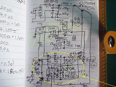
実は、「MPS-3206」の回路図を描き出してみたら、"破壊した個所"は、どうやら1次側、つまりAC側に在ったようだ!(図5、図6[クリック])
しかも、制御精度を高くする為にだろう、トランジスタを入れた高感度の回路構成にしてある。
それがゆえに、オシロのプローブに乗っていたAC電圧に、敏感に反応してしまったようだ。
不覚と言えば不覚だが、経験不足だったわけで、本来なら、こんな場所は、慎重に看るべきで、(市販のACアダプタを電源に使った)オシロなどで、触るべきではなかった!
今後は、気を付けようと思う。

ジャンク「MPS-3206」の"電源が入らない原因"を探ろうとして、オシロ(「SonyTek.326」)のプローブで触って、早々と、「MPS-3206」を壊してしまったのだが、その修復を兼ねて原因を考えてみた。(図2[クリック])
始めは、(終段のMOS-FETへの入力信号を増大する為の)トランジスタ増幅部の"2点間ショート"を想定したが、ピン配置から考えて、それは起き難い。
次に、使っている机が金属製なので、オシロのプローブ線などに、電力線からの大きな誘導電圧が乗り易く、それが原因ではないかとも考えたが、それもかなり起き難い気がする。
更に、Moonlightさんから、"もしかして、AC系分離トランスを使っていないのではないか?"というご指摘があり、AC-DC間の分離状態も考えた。
基本的には「トランス」と「フォトカップラ」で分離されており、それほど低インピーダンスでは結合していないように思う。
しかし、どうやら、スイッチング・レギュレータ/コンバータ類のAC-DC間に入っている"小容量のコンデンサ"が、"リーク"の元凶になりそうだ。(図1)
だが、オシロのプローブにも、1/10モードでは、100KΩ程度の抵抗が入るはずなので、かなり高インピーダンスの状態だから、プローブが"加害者"になるってことは、殆ど想定していなかった。
昔、トランスレス時代の「ラジオ」で、私自身が、良く感電した/させられた記憶があるが、ほゞ、あれに似た話だろうな。
あの時のコンデンサは、0.01μF辺りのチューブラ型だったはずだ。
+++ 破壊部の修復 +++
AC-DCコンバータ回路を調べていて、それらには常に、(静電気放出用だと思うが)小容量のコンデンサが、AC-DC間に入っていることに気が付いた。(図1)
調べるのに使っていたオシロは、先日買ったSonyTek.326ジャンクだが、これには、(高度の絶縁性は考慮されていない)ACアダプタが使われていて、そこにも、恐らくAC-DC間に小容量(数〜数百nF)のコンデンサが入っているはずだ。
もし、ACプラグの差し方が、お互いに逆で、「MPS-3206」のトランジスタの入力部が、高インピーダンス状態であれば、AC100Vの大半が掛かる可能性がある。
そして、その後段は、大電力用MOS-FETだから、それに応じた電流を流したに違いない!
その大電流が、(こんな箇所まで壊すのかと、疑問に思うほど広く)周りの部品を壊してしまったようだ。(図4[クリック])
(他の理由で)壊れたものを修理するのが、本趣味だが、自分で壊してしまったのも、やはり修理しなければ!
ということで、"壊したパーツ類"は、既に発注済だ。
(電源自体は、"セミ・プロ"による手作り感が残っていて、あまり"重厚さ/高級感"を感じないので、少々物足りない)
MPS-3206 Junk, destruction cause [2020/12/05]

+++ Addendum +++
Actually, when I drew the circuit diagram of " MPS-3206 ", it seems that the "destroyed part"was on the primary side, that is, the AC side ! (Fig.5, Fig.6 [click})
Moreover, it has a highly sensitive circuit configuration with transistors, which is probably to improve control accuracy.
Therefore, it seems that it has reacted sensitively to the AC voltage on the oscilloscope probe.
Anyways, I was unconscious because was inexperienced, so I should have watched such a place carefully and should not touch it with an oscilloscope (using a commercially available AC adapter as a power source)!
I will be careful in the future.
At trying to find the " the cause of the power not turning on "of the junk " MPS-3206 ", the oscilloscope (" SonyTek. 326 ") probe broke " MPS-3206 "by touching at an early stage, but I was also to repair it, I thought about the cause. (Fig.2 [click])
At first, I assumed a "short-circuit between two points"in the transistor amplification section (which is to increase the input signal to the final stage MOS-FET), but considering the pin layout, that is unlikely to occur.
Next, since the metal desk I'm using, it's easy to get a large induced voltage from the power line on the probe line of the oscilloscope, and I thought that might be the cause, but I feel that it is quite unlikely to happen.
Furthermore, Mr. Moonlight pointed out that "Isn't it because not using the AC to DC separating transformer ?".
So I considered the separation state between AC and DC of the switching regulator.
Basically, it is separated by "transformer"and "photocoupler", and it seems that they are not coupled at such low impedance .
However, apparently, the "small value capacitors"between the AC line and DC line of the converters seems to be going the " cause of leak ". (Fig.1)
However, the oscilloscope probe have a resistance of about 100KΩ in 1/10 mode, so the probe is in a fairly high impedance state.
So I almost never expected to happen that probe becomes " perpetrator ".
A long time ago, I remember i was attacked repeatedly by electrocuted(?-.-:) on the "the transformerless type radio ", but it's probably the similar story as that.
The capacitor at that time must have been a tubular type around 0.01μF.
+++ Repairing of destroyed area +++
I was looking into the AC-DC converter/switcing regulator circuits and noticed that the most of them always had been connected with a small capacitor (for electrostatic discharging ?) between AC and DC. (Fig.1)
The oscilloscope I was using to look up was the SonyTek.326 junk I bought the other day, but it AC adapter (no account about high insulation) is used, and it probably also contains a small capacity (several to hundreds of nF) capacitors between AC and DC !
If the AC plugs are plugged in the opposite way and the input of the " MPS-3206 "transistor is in the high impedance state, most of the AC100V may be applied to a target of probe.
And since the subsequent stage is a high-power MOS-FET, it must have passed the large current by according to faked voltage ! That current seems broke the surrounding many parts (It unbeleabale !). (Fig.4 [click])
My hobby is to repair broken things by other reasons, but I still have to repair what I broke !
Then, the "broken parts"have already been ordered.
(The power supply itself is a little unsatisfactory because it still remaine a feeling the handmade by semi-professional and does not feel "profound/luxury".)
MPS-3206ジャンク 失敗 [ English Note ] [2020/12/01]
 [クリック]→図2:ジャンクMPS-3206の前面")
30V前後で2A以上の"可変DC電源"で、デジタル式でコンパクトなものを、(ジャンクでも良いから)安価で手に入れたいと、常々考えているのだが、今回は、焦って、ジャンク品の"選択"に失敗した。
元々、私は、旧くて・実績のある・質の良い高級品(高価でもある)ジャンク、あるいは、それの故障品を安価に入手して、修理して使うというのが、私の好みだ。
だから、新しい製品は、極力、敬遠している。価格は高いし、"初期不良"や"長期安定性が不明"だし、長く楽しめないものが多いからだ。
(その点、"百均グッズ"は良い!ダメなら、気楽に捨てられる!)
今回は、うかうかと「YouTube」上の宣伝に乗せられて、それの"不動ジャンク"に興味を持ってしまった。
買った「MATRIX MPS-3206」は、"電源が入らないジャンク"という説明だった。
しかし、実は、電源は入っていて、中は生きていたようだ。
どうやら、"表示"や"電圧"を集中制御するμC(1チップ・マイコン)が働いていなくて、"電源入らず"の様相を呈していたらしい。(図2[クリック])
分解出来るところまで分解して、μC(STM32L151C8T)の動きを確かめたが、結局、それが動いていないことが分かった。...あーこりゃ、ダメだ!(図1)
"μC"の持つ機能がこの製品の肝だろうし、それが不良化しては、もう製品の意味が無い!
そして、このような故障は、"素人修理"などは、到底無理!
(しかし、こんなのは初期不良の一種で、「返品・交換」が常道なんだが、3Nのオークションではねぇ)
この製品の"発想"は、悪くないと思うが、"製品化力"が、まだ不足なのでは?
 [クリック]→図2:うっかりミス(ショート)で、可変電圧系の全面破壊")
+++ 2系統の電源、可変電圧系の破壊 +++
当初、"電源が入らない"のは何故か?と疑って、電源基板の方をオシロで調べていたのだが、プローブの先でトランジスタの足を触った時、バシッ!と大きな音がして、煙が出た!(しまった!高電圧をショートさせてしてしまったらしい)
何だ?...ここまで、電源が来ているではないか!?
このショートで、主系統の"32V可変電圧系"が、全滅状態になっていた。
オシロのプローブの先が、
...後日、原因が判明。オシロの電源(非絶縁型ACアダプタ)が元凶。
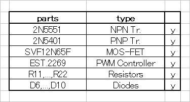
被害は、MOS-FET(SVF12N65F)や、その横の大型抵抗 0.16Ω/1W、トランジスタ2個(Q2,Q3)、抵抗5個(R10,R11,R13,R14,R22)、ダイオード3個(D8,D9,D10,)などに、いずれも"焼け焦げ"が出来るほどの大電流が流れたらしい。(図4[クリック])
大元の「ACヒューズ」は切れずに、基板上の部品群が、全壊したわけだ。(えー?この方が、安全なのかな?)
不幸中の幸いで、"12V固定電圧系"の方は活きていた。
なので、それを使って、前側の「制御基板」に電源を供給して、μCなどの動きを調べてみた。(図3)
更に分解して、μC(STM32L151C8T)やLED駆動系(TM1640)などの端子が見えるようにして、それらをオシロで調べてみると、これらのデバイスのどの端子にも、動作している"動き"が、全く見えない。
μCの端子#4、#6に、クロック信号が出ていない!壊れているのか?
...もしかして、μCの最大定格(4.0V)が低過ぎて、"32V系、12V系電源”に対応出来なかったのかな?
因みに、外部入力によってμCが"全く動作しないケース"や、"内部クロックが停止するケース"などを、技術資料を基にして考えてみたが、思い当たる節が無い。
多分、"NMI(相当)端子"を、外部から強制的に抑え付けていれば、停止したままかもしれないが、「主制御部」にそんな機構を設けるなら、別途「警報器」などを備えておくべきだし、それも大いに疑問だ。
結局、本来はメーカーが、無償で回収して改善策を施すべき"初期不良品"をジャンクとして買ってしまったようだ。(阿呆草!)
I always want to get a digital and compact"variable DC power supply" of 30V or more 2A at a low price (because it can be junk). I'm thinking, but this time I was impatient and failed to"select" junk items.
Originally, I prefer to get old, proven, good quality (also expensive) junk, or its defective ones at a low price, repair them, and use them.
Therefore, I avoid new products as much as possible. The price is high," initial failure " and"long-term stability unknown ", and there are things that I can't enjoy for a long time. Because there are many.
(In that respect,"100-yen goods" are good ! If they don't work, they can be easily thrown away !)
This time, I was interested in the"immovable junk" of it because of the promotion on" YouTube ".
The" MATRIX MPS-3206 " I bought was explained as" Junk that doesn't turn on ".
However, in fact, the power was on and it seems that the inside was alive.
Apparently, the μC (1 chip microcomputer) that centrally controls the "display" and "voltage" was not working, and it seemed to be "power off". (Fig.2 [click])
After disassembling to the extent that it could be disassembled, I finally confirmed the movement of μC ( STM32L151C8T ), but found that it was not working. ... Oh, this is bad ! (Fig.1)
The function of "μC" is the heart of this product, and if it becomes defective, the product is meaningless anymore !
And, for such a failure,"amateur repair" etc. is impossible at all !
(However, this is a kind of initial failure , and " returns/exchanges " is the usual way, but "sold out" in junk is poor business !?)
I don't think the "idea" of this product is bad, but isn't the "commercialization power" still insufficient ?
+++ 2 power supplies, destruction of variable voltage system +++
Why does it "do not Power On" at first ? I was suspicious that I was looking at the power supply board with an oscilloscope, but when I touched the transistor's foot with the tip of the probe, Bash ! There was a loud noise and smoke came out! (It's done ! It seems that it was shorted a high voltage)
What ? ... Isn't the power coming so far !
Due to this short circuit, the " variable voltage system " of the main system was in the annihilated state .
It seems that the tip of the oscilloscope probe hits both somewhere in Q2 (2N5551) and/or Q3 (2N5401) , which is a catastrophic situation. Seems to have caused.
The damages were MOS-FET (SVF12N65F), a large power resistor 0.16Ω/1W next to it, 2 transistors (Q2, Q3), 5 resistors (R10, R11, R13, R14, R22 It seems that a large current that can cause" burnt " has flowed through the R22) and diode (D8, D9, D10). (Fig.4 [click])
The original "AC fuse" did not blow, and the parts on the board were completely destroyed. (Eh ? Is this safer ?)
Fortunately, the"12V fixed voltage system" was alive.
So, I used it to supply power to the"control board" on the front side and examined the movement of μC and so on. (Fig.3)
If I disassemble it further to make the terminals such as μC ( STM32L151C8T ) and LED drive system ( TM1640 ) visible, and examine them with an oscilloscope, these No working"movement" is visible on any of the terminals of the device.
No clock signal is output to μC terminals #4 and #6 ! Was it destructed ?
... Perhaps the maximum rating of μC (4.0V) was too low to support 32V system, 12V system power supply ?
By the way, I thought about the case where "μC does not work at all" or the "case where the internal clock stops" due to an external input, based on the technical data, but there is no section I can think of.
Perhaps, if the"NMI (equivalent) terminal" is forcibly suppressed from the outside, it may remain stopped, but if such a mechanism is provided in the"main control unit", they should have something like another "isolated alarm".
After all, it seems that what I bought as a junk was originally an "initial defective product" that the manufacturer should collect and take remedial measures.