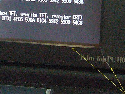
However, I thought that this would be the best way to use the "6-inch TFT module" on hand. (Fig_1)
It is inevitable that the screen will be on the left, but the result has been properly settled ! (And self-portrait self-sponsored ♪ Fig_2 click)
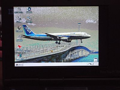
It was good until here, but the tint of the image of this "TFT module" feels strange.
It seems that the color of the dark color is different.
Also, I used Wireless LAN, but I can not read “Encrypted sites (https: // ...)”!
In other words, there is also a problem that there is no browser that can be read (there are many, but they can not be used on Win95 ).
This is due to the oldness of IBM PalmTop PC110 , but I do not want to think it is the limit of this machine!
As it is good for convenience, I would like to think of a way to read the internet sites somehow.
![Fig_3 : used cutter nife an nibbler [click]→Fig_4 : setting the 6-inch module](fig/dspimpsc.jpg)
+++ Cut front frame ane set TFT module +++
The formation of the front frame (removal of internal ribs and cutting of the edges) was done using "Nipper", "Pliers", "Cutter" or "Nibler". (Fig_3)
In the case of such old plastic plates, the use of a "Nibler" has the risk of cracking or even spreading if care is not taken.
However, it is the charm of it to cut with crispy!
The grooving with the "cutter" was quite careful, as there was a tendency for the "grooves" to bend, but again I failed one place! (Described later)
The “6-inch TFT module” was placed completely inside the front frame, toward the right.
The toothpick was cut to a thickness of 1 mm and attached to the bottom. (Fig_4 click)
Finally, I fixed the important parts around the "TFT module" with "hot-melt bond".
(This has only the effect of "shift". There is almost no bending strength etc.)
![Fig_5 : bending the FFC [click]→Fig_6 : putting the connectores plate](fig/dspimpse.jpg)
+++ Bending the LCD FFC +++
The position of the “FFC terminal of the 6-inch TFT module” of the DTN-6500 (Portable Navi) device is considerably shifted to the left.
So, as it is, it is difficult to place the FFC terminals and the FFC terminal connectors and boards of PC 110 on the same plane.
(The last time there was a break in the FFC for liquid crystal, and it was replaced, so there was room in length and it was easy to adjust the position. )
This time, I tried to see if it was possible to adjust the position by bending "FFC for PC110 -DSTN liquid crystal".
It seems that it is quite so by bending at 2 places ♪ (Fig_5)
However, since "substrate with connector" has only "30-pin" and "40-pin", only "lower-pin type connector" remains, these are used in the reverse state.
The connection was performed in the reverse state. (Fig_6 click)
"Slim copy sheet of number sequence" was pasted so that "number" of "land group" is not mistaken. (See the arrow in Fig_6)
(I tried to put two substrates in parallel and side by side this time to imagine what would happen if they were to be one printed circuit board)
![Fig_7 : Connection completion status [click]→Fig_8 : Connection status (face down)](fig/dspimpsg.jpg)
+++ Connection completion status +++
For the wire connection, a heat-resistant coated wire outer diameter of 0.7 mmφ was mainly used. (Fig_7)
(But the number of colors is not enough, the result is a hybrid)
The interconnections were as per the interconnection table ( Table_S ) (as is conventional).
The only mistake was that all of the GND lines were left untouched, eventually all connected to No. 1 and passed !
The connection with the connector is performed by turning over both substrates.
A common copy sheet was used for separation from the pedestal (the back of the TFT module). (Fig_8 click)
The upper side (upper lid side) is also the same.
The cushioning material was not particularly caught, and the cushioning property of the wiring group was utilized.
Now, I closed the back cover and screwed in 6 places, it seems to have been properly stored. Completed!
Essentially, if it is the quality of work in Japan, parts will be firmly fixed and fixed, but amateurs do not go there. (Wry smile)

+++ 2 bugs +++
This time, the connection seems to be well done and it works with one shot.
However, it is necessary to set "HDD-2" as the first drive in "BIOS settings" by using both " Port-replicator " and " External Display " as usual.
After the "TFT display" comes out, the two areas that I worries are the " Crack " and the " Over-cut " in the front frame. (Fig_9)
"Crack" is not bothered much, but "Over-cut" is a bit annoying depending on the state of the screen.
(It would be fine if I put a black sheet inside, but now it's spoofed with a black-color-pen "choi-choi♪")
There was no problem when working on this machine on "Port-replicator"
But,if the machine works stand-alone, it becomes unstable power turn on or off. If I push down the DC plug with my finger, it is become stable state.
...it may cause cracks of the solder at the "terminal of power-receptacle".
To repairing needs to be disassembled until a very deep place, but I worry whether I can it be disassembled / reconstructed without damaging other parts.
And, if I ask myself, I'm not confident.

+++ coloring failure +++
I was using Win95-CF to run Win95 and change the wallpaper, it is "Color" is not so good ! (Fig_11)
The color is pale or looks different.
For comparison, the same wallpaper put on the previous "5-inch TFT" machine, those seem to be not so bad on the 256 colors mode. (Fig_12 click)
The possible cause of this failure may be the "misconnection" of the "low_bit line".
Alternatively, it may be an error in the "interconnection table" or a difference in the "TFT module".
Let's check this in the future.
However, if the image is less colored, it may look like a "bright picture", which is a very difficult thing to discard. . . I think. d^-^;
![Fig_13: Hypothesis of WEP-AP <click>-> Fig_14: temporary dummy site [http:// ...]](fig/dspimpsm.jpg)
+++ Can't browse the Internet site ? +++
Few years ago, after upgrading the encryption level of the wireless LAN to WPA2, with the WEP mode used in the " PC110 " group has not became to connect.
This time, I added temporarily a WEP dedicated AP. (Fig_13)
Now, " PC110 " group of wireless LAN system should have become available, but they can't connect to the public site on the internet and Grakutaen site can't connect also.
In the past, it was possible to connect because any sites was "http: // ..." (no encryption), but after being switched to "https: // ..." (encryption) such sites became unviewable.
I don't know wether exist any special browser (for encryption-enabled) being able to run on Win95 or Win98 .
For a test, I made a "http: // ..." site (cover only). ...It looks like right. (Fig_14 click)
But it is not enough at all ! Seeking a way to progress.
![図1:[IBMロゴ]入り前パネルの加工と位置関係 [click]→図2:改造後の全景](fig/dspimpsa.jpg)